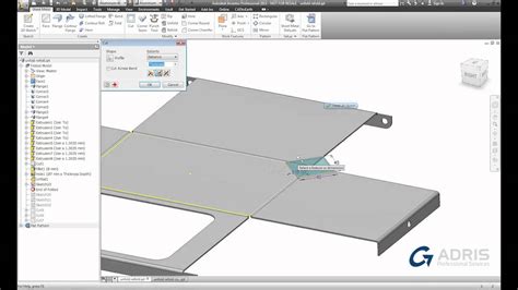
drawing sheet metal parts in inventor To set the parameters, click Sheet Metal > Setup > Sheet Metal Defaults on the ribbon; the Sheet Metal Defaults dialog appears. This dialog displays the default preferences of the sheet metal .
does the 2011 NEC code allow burial of a conduit body like this? its not being used as a junction box, just need a spot to pull wire through one port twice, etc.
0 · sheet metal inventor tutorial pdf
1 · inventor unfold sheet metal
2 · inventor sheet metal thickness
3 · inventor sheet metal flat pattern
4 · inventor sheet metal exercises pdf
5 · inventor convert to sheet metal
6 · inventor change sheet metal thickness
7 · create flat pattern inventor
$379.99
The flat pattern view is useful for fabrication, and is the only view that supports sheet metal annotations. You can create a folded model view and a flat pattern view for a sheet metal part .You can create sheet metal parts in several ways. Create a sheet metal part using .
Within the Autodesk Inventor design environment, a sheet metal part can be .

Create and edit sheet metal parts in Inventor.You can create sheet metal parts in several ways. Create a sheet metal part using the sheet metal template. The template uses your settings for material thickness, bend radius, and corner .
To set the parameters, click Sheet Metal > Setup > Sheet Metal Defaults on the ribbon; the Sheet Metal Defaults dialog appears. This dialog displays the default preferences of the sheet metal . How to start sheet metal part in inventor? In part 22 of the Autodesk Inventor 101: The Basics series, we'll take a look at how to use the basic functionality of the sheet metal.
sheet metal inventor tutorial pdf
Within the Autodesk Inventor design environment, a sheet metal part can be displayed as a folded model or a flat pattern. With sheet metal commands, you can unfold features and work on a model in a flattened state, and then refold .

Create and edit sheet metal parts in Inventor. A look into creating drawings of Inventor sheetmetal components and flatpatterns
In this session, we’ll start from scratch and create a sheet metal part to generate a flat pattern, export a DXF cut file, and create drawings with dimensioned bend lines. Discover best practices, things to avoid, and practical advice.
Master the fundamentals of sheet metal design using Autodesk Inventor in this 2-day course. Learn to form sheet metal parts, assemblies, and drawings.
inventor unfold sheet metal
Autodesk Inventor now has integrated sheet metal tools that make it easier to design with sheet metal. In this Inventor 101 video, we’ll take you through all of the sheet metal design basics you’ll need to know to get started .
The flat pattern view is useful for fabrication, and is the only view that supports sheet metal annotations. You can create a folded model view and a flat pattern view for a sheet metal part or iPart (The Flat Pattern option is available only if a flat pattern exists in the source file.)You can create sheet metal parts in several ways. Create a sheet metal part using the sheet metal template. The template uses your settings for material thickness, bend radius, and corner relief. You use sketch commands to create a profile for a base face or an initial contour flange.
To set the parameters, click Sheet Metal > Setup > Sheet Metal Defaults on the ribbon; the Sheet Metal Defaults dialog appears. This dialog displays the default preferences of the sheet metal part such as sheet metal rule, thickness, material, and unfold rule. You can change these preferences as per your requirement. 2. How to start sheet metal part in inventor? In part 22 of the Autodesk Inventor 101: The Basics series, we'll take a look at how to use the basic functionality of the sheet metal.
Within the Autodesk Inventor design environment, a sheet metal part can be displayed as a folded model or a flat pattern. With sheet metal commands, you can unfold features and work on a model in a flattened state, and then refold the features. You create sheet metal parts from a template file.Create and edit sheet metal parts in Inventor.
A look into creating drawings of Inventor sheetmetal components and flatpatternsIn this session, we’ll start from scratch and create a sheet metal part to generate a flat pattern, export a DXF cut file, and create drawings with dimensioned bend lines. Discover best practices, things to avoid, and practical advice.Master the fundamentals of sheet metal design using Autodesk Inventor in this 2-day course. Learn to form sheet metal parts, assemblies, and drawings. Autodesk Inventor now has integrated sheet metal tools that make it easier to design with sheet metal. In this Inventor 101 video, we’ll take you through all of the sheet metal design basics you’ll need to know to get started with this type of material.
inventor sheet metal thickness
The flat pattern view is useful for fabrication, and is the only view that supports sheet metal annotations. You can create a folded model view and a flat pattern view for a sheet metal part or iPart (The Flat Pattern option is available only if a flat pattern exists in the source file.)You can create sheet metal parts in several ways. Create a sheet metal part using the sheet metal template. The template uses your settings for material thickness, bend radius, and corner relief. You use sketch commands to create a profile for a base face or an initial contour flange.

To set the parameters, click Sheet Metal > Setup > Sheet Metal Defaults on the ribbon; the Sheet Metal Defaults dialog appears. This dialog displays the default preferences of the sheet metal part such as sheet metal rule, thickness, material, and unfold rule. You can change these preferences as per your requirement. 2. How to start sheet metal part in inventor? In part 22 of the Autodesk Inventor 101: The Basics series, we'll take a look at how to use the basic functionality of the sheet metal.Within the Autodesk Inventor design environment, a sheet metal part can be displayed as a folded model or a flat pattern. With sheet metal commands, you can unfold features and work on a model in a flattened state, and then refold the features. You create sheet metal parts from a template file.Create and edit sheet metal parts in Inventor.
A look into creating drawings of Inventor sheetmetal components and flatpatternsIn this session, we’ll start from scratch and create a sheet metal part to generate a flat pattern, export a DXF cut file, and create drawings with dimensioned bend lines. Discover best practices, things to avoid, and practical advice.Master the fundamentals of sheet metal design using Autodesk Inventor in this 2-day course. Learn to form sheet metal parts, assemblies, and drawings.
yellow house with charcoal metal roof
yellow house metal roof color
We offer flexibility in style, options, and accessories with our two story metal building kits. Take your metal building to the next level with Quicken Steel.
drawing sheet metal parts in inventor|inventor change sheet metal thickness